10 August 2014

590. Home-made Titrino tip

Metrohm make a range of autotitrators called titrino, titrando etc. While they are great, they are expensive (ca AU$15,000 +/- 5,000) -- and the parts are ridiculously overpriced. For example, a simple pH electrode cable costs AU$100-150, which isn't a good use of taxpayer money.


I'm also not a big fan of their titration tips, one of which is shown in the photo below

The piece in this photo costs AU$30:
AU$30 -- reasonable?

Besides, in my own experience they don't work as well as the home made tips we used in a lab I used to work in.

So, here's a description of an alternative type of tip for doing titrations with a titrino.

The design in my old lab:

This is the tip -- it's a glass capillary which is connected to 1/16 PTFE tubing using a piece of elastic silicone tubing
The titrino is connected to the 1/16 PTFE tubing via an M6 (or 1/4-28) PTFE union.
The PTFE tubing is connected to the union using an 1/4-28 (or M6) ferrule
Like this

In my current lab:
Since I wasn't sure what the size of the capillary and the connecting silicone tubing was, I had to guess, and used the following parts:

Capillary OD 0.66 mm ID 0.5 mm
Silicone tubing OD  3 mm ID 0.5 mm
PTFE tubing 1/16 (ID 0.5 x OD 1.6 mm)
1/16 ID and 1/4 OD PEEK Ferrule
1/4-28 PTFE connector

It basically came down to what I could order online from a Chinese equivalent to ebay called taobao.

NOTE: the capillary here doesn't go that great with the silicone tubing, so I had to glue it using silicone glue. A smaller ID silicone tubing or a larger OD capillary might work better. Note also that you'd want as thin a capillary ID as possible though to avoid diffusion and leakage.

Here's the assembly (the glass capillary is a bit short since it broke):
And here's the capillary with the silicone part (the light in my office is pretty bad).
I used silicone glue to fix the capillary in place:
Some more photos of the different parts:
Very affordable Chinese capillaries -- $5 for 1,000!

1/16 inner and 1/4 outer diameter PEEK ferrule

The PEEK ferrule and the M6 (1/4-28) union


02 August 2014

589. Gnome-shell 3.12.2 -- another feature gone

The Gnome team has been removing feature after feature from different gnome-related applications. In the current version of gnome-shell (3.12.2-3) on debian testing (jessie) there's yet another feature gone -- you can't access the audio settings from the desktop.

Whether you use right- or left-click on the audio icon, you get the same menu. Clicking on the audio (left- or right-click) icon in that menu only causes the volume to go to zero.


Instead, the only way to access audio settings is now via the system settings which takes longer and involves more clicks. It's a minor nuisance if you're used to how gnome has previously worked.

29 July 2014

588. ata6: SRST failed (errno=-16) AND disk-by-uuid does not exist

The problem:
I've been having boot issues with one of my nodes. Everything is fine up to and past GRUB:

Then this happens:
[21.405411] ata6: SRST failed (errno=-16)

And typically I get dumped in a shell:
ALERT! /dev/disk/by-uuid/xxxx does not exist

Towards the solution:
blkid shows both disks:
blkid


Either way, turns out the way to get the system to boot is pretty simple. Type exit and hit enter.

exit leads to successful boot
Looking at dmesg this is what happened:
[ 1.998149] usb 2-1: Product: USB Optical Mouse [ 2.005374] input: USB Optical Mouse as /devices/pci0000:00/0000:00:12.1/usb2/2-1/2-1:1.0/input/input1 [ 2.005452] hid-generic 0003:0461:4D81.0002: input,hidraw1: USB HID v1.11 Mouse [USB Optical Mouse] on usb-0000:00:12.1-1/input0 [ 6.476845] ata6: link is slow to respond, please be patient (ready=0) [ 11.465026] ata6: device not ready (errno=-16), forcing hardreset [ 16.665379] ata6: link is slow to respond, please be patient (ready=0) [ 21.485411] ata6: SRST failed (errno=-16) [ 26.685767] ata6: link is slow to respond, please be patient (ready=0) [ 31.505806] ata6: SRST failed (errno=-16) [ 31.894576] uhci_hcd: USB Universal Host Controller Interface driver [ 36.706152] ata6: link is slow to respond, please be patient (ready=0) [ 66.579156] ata6: SRST failed (errno=-16) [ 71.611367] ata6: SRST failed (errno=-16) [ 71.623705] ata6: reset failed, giving up [ 105.133562] PM: Starting manual resume from disk [ 105.133565] PM: Hibernation image partition 8:2 present [ 105.133567] PM: Looking for hibernation image. [ 105.133775] PM: Image not found (code -22) [ 105.133777] PM: Hibernation image not present or could not be loaded. [ 105.189165] EXT4-fs (sda1): mounted filesystem with ordered data mode. Opts: (null) [ 107.565728] udevd[725]: starting version 175


Fixing it:
Increase the rootdelay so that the harddrive(s) have time to boot up. I think in my case the issue is that I found an ancient IDE drive which may be slow to spin up, and maybe even failing (I use it for /scratch).

Either way, edit /etc/default/grub and add rootdelay=90 (for example) to the end of GRUB_CMDLINE_LINUX_DEFAULT, e.g.
GRUB_CMDLINE_LINUX_DEFAULT="quiet splash vga=0x0318 text rootdelay=90"
Then do
sudo update-grub

and hopefully the next time your system will boot, although slowly.

28 July 2014

587. Very Briefly: Getting pictures off of a corrupted Compact Flash card using testdisk

Nothing terribly complicated here. My CFII card (above, at /dev/sdb1)  is about a decade old and occasionally becomes corrupted. To recover the photos I use photorec which is part of testdisk:

sudo apt-get install testdisk
sudo photorec

Select the correct device, in this case /dev/sdb

Search

Pick the correct file system, typically FAT16 or 32
Also select a place to store the recovered photos. Then recover:


And you're done.

586.Very Briefly: Gnuradio, RTL-SDR, GQRX and an R280T device on debian jessie

NOTE:
* I did this on debian jessie which at the time has gnuradio v 3.7.3-9+b1 and rtl-sdr v 0.5.3-3

* I'm having a lot of trouble getting gqrx working on debian wheezy even with backports. Whereas the backports versions of gnuradio, rtl-sdr and gqrx-sdr install just fine, when running gqrx I get the following error:
gqrx: symbol lookup error: /usr/lib/x86_64-linux-gnu/libQtNetwork.so.4: undefined symbol: _ZN16QIODevicePrivate13putCharHelperEc
* gqrx won't work on debian wheezy systems with 2 Gb of memory for some reason. I get the same error as is shown in this post: https://groups.google.com/forum/#!topic/gqrx/20F8RMWkNbU

The post:
I recently bought a DVB USB dongle based on RTL2832 and R280T: http://www.ebay.com.au/itm/221450623699?ssPageName=STRK:MEWNX:IT&_trksid=p3984.m1497.l2649. AU$11for a TV card which actually works flawlessly under linux really isn't bad!

As I already have a mythtv setup using leadtek DTV 1000S I was more interested in exploring the R820T dongle as a software defined radio (SDR).

 So, after glancing at  http://www.thepowerbase.com/2012/06/getting-started-with-rtl-sdr/2/ I did the following


sudo apt-get install rtl-sdr gnuradio gnuradio-dev libgnuradio-osmosdr0.1.1.4 git libboost-dev liblog4cpp5-dev libboost-system-dev libboost-program-options-dev checkinstall
mkdir ~/tmp
cd ~/tmp
git clone https://github.com/csete/gqrx.git gqrx.git
cd gqrx.git/
mkdir build
cd build
qmake ../
make
sudo checkinstall --install=no
0 - Maintainer: [ root@niobium ] 1 - Summary: [ gqrx ] 2 - Name: [ gqrx ] 3 - Version: [ 20140726 ] 4 - Release: [ 1 ] 5 - License: [ GPL ] 6 - Group: [ checkinstall ] 7 - Architecture: [ amd64 ] 8 - Source location: [ build ] 9 - Alternate source location: [ ] 10 - Requires: [ ] 11 - Provides: [ build ] 12 - Conflicts: [ ] 13 - Replaces: [ ]
sudo dpkg -i gqrx_20140726-1_amd64.deb

Starting gqrx and using it is easy:
gqrx
So far I haven't managed to get anything other than regular commercial radio signals (I've only explored the FM band).

17 July 2014

585. Very briefly: use latex to combine .eps files into a single .eps

Say you have a figure made up by several smaller images by combining several includegraphics statements. Say also that you need to submit the figure as a single file when uploading the final version of your article.

The first step is to make sure that the output .ps file fits flush to the figure (see http://texblog.org/tag/fit-page-to-content/) using the standalone class:
 
\documentclass[varwidth=true, border=10pt, convert={size=640x}]{standalone} \usepackage[english]{babel} \usepackage{graphicx} \begin{document} \begin{figure}[h] \begin{center} \includegraphics[width=2.0cm]{figure_1a.eps} \includegraphics[width=2.0cm]{figure_1b.eps} \includegraphics[width=2.0cm]{figure_1c.eps} \\ \includegraphics[width=2.0cm]{figure_1d.eps} \includegraphics[width=2.0cm]{figure_1e.eps} \end{center} \end{figure} \end{document}
Then use ps2eps to turn the ps into an eps file:

ps2eps combined_image.ps

24 June 2014

584. Build your own pH meter (analogue)

A few years ago a friend of mine with a degree in engineering helped me build a simple pH meter. In terms of quality of the readings there is no difference between it and our $15,000 titrino.

Either way, I'm putting the description of it online here in case other people are interested. Note that 'we' designed it based on what we found available from various websites, so the design is hardly unique.

Also note that it requires a multimeter/voltmeter to get a reading -- there's no USB/serial output or anything fancy like that.

(in related news I'm planning on taking night classes in electronics at a local TAFE (which is like a community college) so that I can start building more instruments/toys myself. A potentiostat would be nice...)

Anyway, back when we built this we ordered the parts from Digikey (I lived in the US at the time), and here's a list of what we got as shown on the invoice (the parts numbers of the linked items differ in some cases -- I presume that they are the same, but cannot guarantee that they are.
* Note that you'll need more than one of some items.
* Note that the parts includes stuff for using a whiteboard/prototyping board i.e. we first made a non-soldiered version, and then made a permanent assembly. 
* The stuff for the final pH meter (i.e. the stuff in the pomona box) is shown in red
* The stuff for connection the pH meter to a voltmeter/multimeter is shown in blue
* The stuff that's needed for the power supply is in bold black
* Stuff that I ordered at the same time but can't remember what we used it for is in the default colour (i.e. black)

Price     Item number               Description       
(USD)    (Digikey)
---------     ---------------------                --------------------      
3.05       LMC6081IN-ND      IC OP AMP PREC CMOS SINGLE 8-DIP  
2.96       ACX1046-ND          Conn. enc. bulkhead female jack x 2
3.78       7-1437529-5-ND     Conn socket dip 8 pos gold T/h

7.71       J6212-ND               BNC cable        

8.07       501-1032-NB          BNC female-dbl banana
47.85     945-1081-ND          Converter AC/DC 15W +/-12V out DL T/H


In addition, looking at the board (see pictures below), you'll also need
3 x female banana sockets
2 x K5M104(?) capacitor (x 2)
2 x BC1020TR-ND BC102 capacitor (x 2)
3 x female banana sockets
and lots of wires.


You'll measure the potential (emf) using a voltmeter, and by calibrating  the potential against a set of pH standards you can calculate the pH. In theory 0.0 mV should be at pH 7, and the potential should increase ca 59 mV per pH unit, so that pH 6 is +59 mV and pH 8 is -59 mV.

Whether this is actually true (it won't be) depends on your pH electrode, temperature, ionic strength etc.

pH box:
Add caption

Annotated view


The BNC cable is connected to a double banana contact, which attaches to the voltmeter


Power supply:
You can get a proper one, or build one yourself. I did the latter. It ain't pretty -- in fact, the following pictures should horrify you. NOTE: unless you know what you are doing you MIGHT DIE! Playing with high voltage stuff may also be ILLEGAL for unlicensed people in some jurisdictions.


Power OUT -- +12 and -12 V, and ground.

Power IN

Green goes from Ground IN to the ground pin on the right on the power supply. The thin yellow wire then goes to the ground pin on the left on the power supply. The fat yellow wire then goes to the ground out banana plug. If your ground touches ANY of the other pins you may ELECTROCUTE yourself.


583. Very, very briefly: using a USB graphics card with a headless box

This is an 'It Works' post. No tips or tricks, simply a report of something that works out of the box.

I've got a tiny server which has the following ports:
2 x USB type A, 4 x RJ45/8P8C (eth), 1x DE-9 (RS-232). There's no VGA out.

While this isn't a real problem -- I normally install linux on it either via a chroot or via a virtual machine by hooking up the HDD via a HDD-> USB cable to another computer -- it would be nice to be able to hook up a monitor to the server, in particular as I'm thinking about turning it into a lab computer to use for measurements. That it's so portable (21 x 15 x 4 cm) is an added bonus as it allows us to move it between labs.

Anyway, I bought an FY-1650  USB-to-VGA card (see e.g. here and here) for ca AUD 37 on ebay:

lsusb gives 
Bus 001 Device 003: ID 17e9:019e DisplayLink


I currently run debian wheezy (i386) on the server. Plugging in the card and a monitor and booting up everything worked without needing to do anything.

NOTE: by working I mean that I get the terminal -- I haven't tried this with a full desktop environment such as gnome, xfce etc.

Very happy...


13 June 2014

582. Briefly: freecall.com using linphone

I've covered how to set up linphone in the past: http://verahill.blogspot.com.au/2011/08/linphone-with-iinet-iitalk-voip-service.html

This is thus going to be a very brief post with just the settings for freecall.com, which offers a SIP service.

The specific settings that you need to make are (this is from my ~/.linphonerc
[auth_info_0] username=myUserId userid=myUserId passwd=PasswordInPlainText realm="sip.freecall.com" [proxy_0] reg_proxy=sip:sip.freecall.com reg_identity=sip:myUserID@sip.freecall.com reg_expires=3600 reg_sendregister=1 publish=0 dial_escape_plus=0

Yes, that's it. So, there you go - you now have a reasonably priced alternative to Skype for international calling.

I've charged my account with 10 Euro, and I've made a few test phone calls. So far so good.

See http://verahill.blogspot.com.au/2014/06/581-obi200-and-debian-and-iinet.html for how to use the obihai 200 ATA with freecall.

12 June 2014

581. Obihai Obi200 ATA and iinet Australia (and freecall)

I've had iitalk sip service as part of my naked DSL via iinet for years, but haven't really done much with it (apart from writing a post: http://verahill.blogspot.com.au/2011/08/linphone-with-iinet-iitalk-voip-service.html). I decided that it might be time to get something akin to a landline, and if it involves buying a new toy, so much better. The toy in question is an ATA device, which allows you to connect your regular old landline phone to your fancy internet router.

I ordered an Obihai OBI200 from Amazon US and had it delivered to Australia.

Getting started was pretty straightforward:
I unpacked the device, plugged in the power cable, and hooked it up to my router via an ethernet cable. I then gave it a static IP address, 192.168.2.131

Next I registered on the obitalk.com website, confirmed my email address, and logged in. You're then offered to set up your device. Note that you'll need to have a phone plugged into your obi device at this point. I bought a $32 Panasonic KX-TG1611 from JB HiFi.

Anyway, go to http://www.obitalk.com


go to dashboard

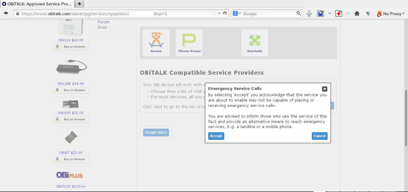
click on SP1

click on Next in the bottom right


select Generic Service Provider
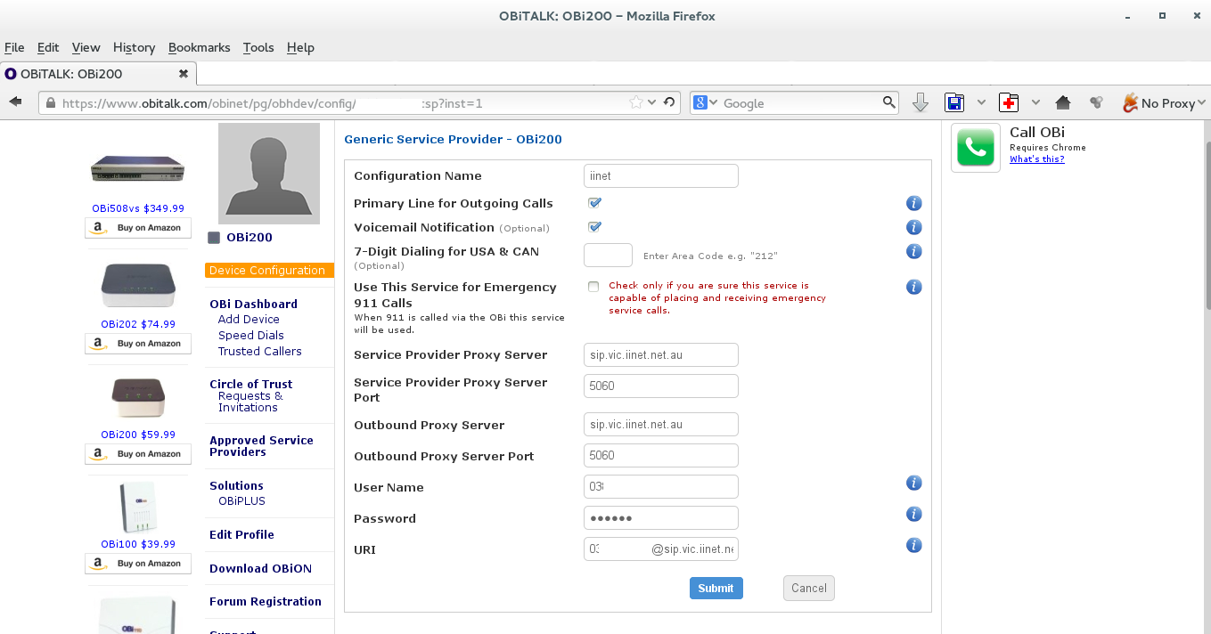
The settings are as follows:
(state=vic, nsw etc. i.e. three-letter code)
Service Provider Proxy Server: sip.state.iinet.net.au
Service Provider Proxy Server port: 5060
Outbound Proxy Server: sip.state.iinet.net.au
Outbound Provider Proxy Server port: 5060
User Name: your phone number (e.g. 03 xxxx xxxx; look it up on your iinet toolbox)
Password: your VOIP password which you set up at some point
URI: yourphonenumber@sip.state.iinet.net.au

Hit submit

If all went well you'll show up as being registered.


freecall.com
I'm thinking about replacing skype with sip, and one provider is freecall.com. I originally signed up with them many years ago because I got a free number, but my account has expired, and they won't let me reactivate it. Either way,  you can still call pretty cheaply using their service.

The settings for the OBI200 and freecall are:
Service Provider Proxy Server: sip.freecall.com
Outbound Proxy Server: sip.freecall.com
User Name: your user name
Password: your password
URI: yourusername@freecall.com

I will work on setting it up for international calls at a later stage.

To select a specific service when making a call, type **1 for SP1, **2 for SP2 etc. See http://www.obihai.com/faq/About-the-OBi/How-do-I-make-calls-with-OBi